
Just recently, I was working on a very cool 1980's Jackson (above). The pickups had been upgraded to Seymour Duncans, and I got to rewire it. The guitar had already been to two different places, but neither of them were able to figure out how to get the wiring to work because the 5-way superswitch (below) is different from others.

(Note that the picture above is not the original wiring. It's one of the failed attempts.) Apparently, this switch was unique to 80's era Jackson guitars. They called it the JE-0005 5-Way Switch, and it was a big selling point that they advertised in their catalogs.
Looking through a Jackson catalog from 1987 on their online archives, I found a picture of a guitar with a similar paint job and a section telling about the switch.


You can see the catalog here: http://support.jacksonguitars.com/catalogs/us/Jackson1987_catalog.pdf
Neither of the places that worked on this particular guitar were able to find information on how to wire it. One of them even called Jackson, but was told that they no longer have the schematic for it. So I went through it with a multimeter and mapped out what connected to what in each position.
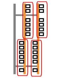
It actually turned out to be pretty straightforward. The switch has four poles. On the diagram below, I've circled the different poles in red. Each pole is completely independent from the others, and has one output with five inputs. The output lug connects to a different input in each switch position.

It actually turned out to be pretty straightforward. The switch has four poles. On the diagram below, I've circled the different poles in red. Each pole is completely independent from the others, and has one output with five inputs. The output lug connects to a different input in each switch position.

As you can see here, I've labeled all the lugs of the switch and shown which ones are connected in each switch position. The lug labeled "O" is the output, and the other lugs are labeled 1-5 according to which position they connect to "O" in. For example: lug 1 connects to "O" in position 1, lug 2 connects to "O" in position 2, and so on, and so on.

I labeled the lugs on my diagram so that they match the lugs of a standard 5-way superswitch with the same label as in StewMac's article here: http://www.stewmac.com/How-To/Online_Resources/Learn_About_Guitar_Pickups_and_Electronics_and_Wiring/Super_SwitchI1.html
With this, you should be able to convert existing guitar wiring diagrams that use a superswitch so that they'll work with a JE-0005 switch.
You rock! Thanks for this
ReplyDelete